Wednesday, September 17, 2014

Macam - macam jenis mesin frais / types of milling machine

Prinsip kerja mesin frais.
mesin frais merupakan mesin perkakas yang banyak digunakan dalam dunia industri manufaktur. mesin ini mempunyai prinsip kerja yaitu pisau pemotong yang diputar oleh spindel. berputarnya pisu pemotong menyebabkan permukaan benda kerja terkelupas, umumnya berbentuk bidang datar.

Gambar proses pengefraisan

mesin frais mempunyai 3 sumbu utama yaitu sumbu Z (searah spindel), Y untuk gerakan lebar dan X untuk gerakan memanjang. benda benda hasil pengefraisan umumnya berbentuk tiga dimensi seperti kubus, segibanyak, profil dan bentuk bentuk lainnya


Gambar beberapa produk hasil pengefraisan


Beberapa macam mesin frais

1. Mesin frais horisontal
Mesin ini mempunyai sumbu horisontal, dan umumnya proses penyayatan dilakukan pada bagian diameter pisau frais / selimut. alat potong mesin frais horisontal umumbya berbentuk diameter besat dan berlubang untuk dipasangkan pada arbor.
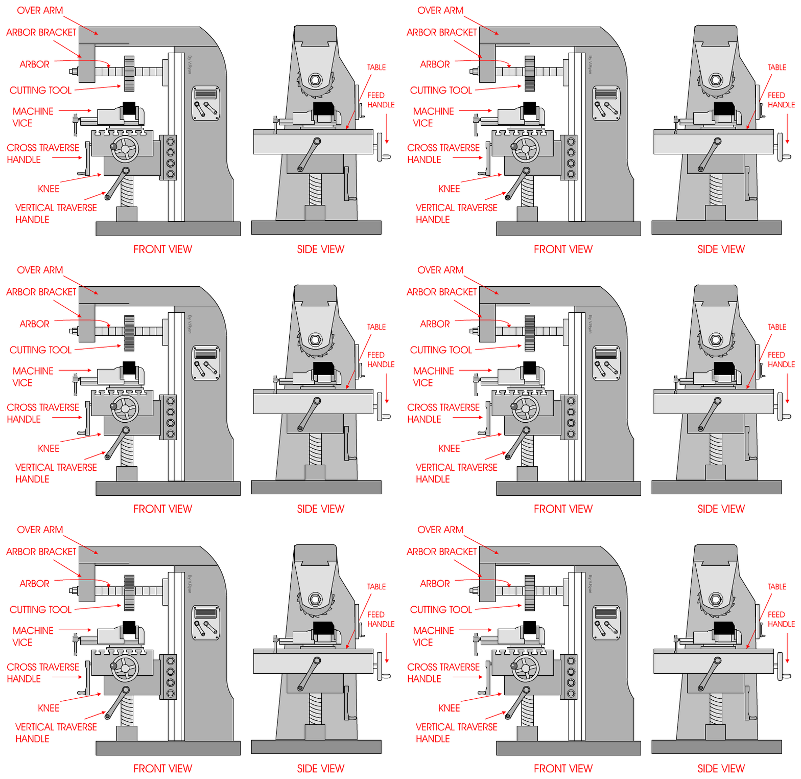
 Gambar mesin frais horisontal dan sistem persumbuan

 Beberapa bagian utama mesin frais horisontal adalah :
1. Table / meja / bed
berfungsi sebagai tempat memasang perlengkapan pencekam benda kerja

2. Over arm dan arbor bracket
Sebagai penyangga perlengkapan pemasangan alat potong / arbor

3. Base
Sebagai landasan mesin

4. Column
Merupakan bagian tegak dari mesin frais sebagai penopang seluruh komponen mesin frais

5. Knee
Sebagai penopang bed dan alas penggerak arah naik dan turun / Sumbu Y

6. Machine vice
Merupakan alat pencekam benda kerja

7. Cutting tool
Berupa pisau frais  / alat pewmotong benda kerja

8. Arbor
Sebagai tempat memasang pisau frais

9. Spindel
merupakan poros putaran utama yang dipasangkan dengan arbor 

10. Cross tranverse Handle
Merupakan penggerak arah Sumbu Z

11 Vertical tranverse handle
Merupakan tuas penggerak arah Sumbu Y

12. Feed Handle
Merupakan tuas penggerak arah sumbu X

2. Mesin frais Vertikal
pada mesin ini spindel mesin terdapat pada posisi vertikal, biasanya digunakan juga untuk proses pengeboran. Prinsip pemotongan pada mesin ini adalah pada bagian muka pisau frais Pada mesin ini biasanya alat potongnya berbentuk batang atau disebut pisau frais jari dan pisau berbentuk Keong / pisau frais muka.

Gambar mesin frai vertikal dan Persumbuannya


3. Mesin frais Universal
Mesin ini merupakan gabungan dari mesin frais horisontal dan vertikal, akan tetapi tidak dapat digunakan secara bersamaan. mesin jenis ini adalah mesin yang cukup banyak digunakan.
Gambar mesin frais universal

4. Mesin frais CNC / Machining center.
mesin frais cnc merupakan mesin frais vertikal yang dikendalikan denagn sistem komputer dan numerik. untuk sistem persumbuan mesin frais cnc ada beberapa macam tipe persumbuan yaitu 3 sumbu, dan 5 sumbu dengan 3 sumbu gerakan lurus dan 2 sumbu gerakan putar. dan dapat membuat pola dalam bentuk 3 dimensi
 Gambar mesin frais 3 sumbu

Gambar mesin frais 5 sumbu

Tuesday, September 16, 2014

Any Types of mechanic thread screw, and chart

Understanding thread is wrapped around the grooves on a steel rod / shaft with a certain size.

The use of so many screw encountered in everyday life, because it serves as a threaded fastener, but it also serves as a screw driver an object. before we know the various types of screw helps us recognize the first part-part threaded.


Here are the different types of screw according to shape

1 Triangle Thread / V Thread

Screw type is a lot we meet, and many of the standard screw which this triangle is there

a. The metric screw / Metric Standard Threads

A triangle with screw tops 60 ° angle and overall dimensions in metric units.

The symbol of this thread is "M" for example is M8 x 1.25 metric thread with a diameter of 8 mm and a pitch of 1.25 mm


b. Whitworth screw / Whitworth Standard Threads

A triangle with screw tops 55 ° angle and the overall dimensions of the unit british

(inches). The symbol of this thread is "W", for example W "x 20 TPI Whitworth screw with a diameter of " and there are 20 Threads per Inch (peak number of threads per inch spacing 1)


c. Threaded pipe / BSP thread (British Standard Pipe Thread)

A standard screw used on pipe joints. symbolized by the letter "R" for example R " standard threaded pipe to the pipe diameter "


d. UNF threaded / Unified Fine Thread

is a kind of screw with combined dimensions of metric and british. This screw has a threaded 60 ° angle peaks and the size dimensions in british units (inches). threaded is mostly used in the United States and Canada. The symbol used is "UNF" UNF example "x 24 TPI UNF threaded  with a diameter of  " and the number of threads per inch 24.

e. UNC threaded / Unified Coarse Thread

a rough version of the screw UNC. rough here meant is the number of threads per inch less than UNF threaded so that it looks rough. The symbol used is "UNC" for example - 16 UNC is UNC threaded diameter "and the number of threads per inch 16


2. Screw Rectangular / Square Threads

is threaded to form a rectangular profile, normally used for heavy loads such as opening the floodgates on the dam and screw on vise. Square Thread symbolized by the letter "Sq" and  example
Sq"x 8 TPI is square thread diameter of  " and the number of threads per inch is 8.


3. Trapezoidal Screw / Trapezium Thread

is threaded with a trapezoidal profile with a peak angle of 30 °. commonly used on the screw drive carriage and leadscrew on a lathe. . This thread is symbolized by the letter "Tr" with metric dimensions 18 x 4 Tr example is the trapezoidal screw with a diameter of 18 mm and a distance of 4 mm screw tops.


4 Screw Acme / Acme Thread

is threaded with a trapezoidal profile with a peak angle of 29 °, commonly used in the carriage and leadscrew. This thread is symbolized by "Acme" with dimensions in inches.


5. Screw Round / Round Thread

Is threaded with a semi-circular profile in the valleys and peaks thread. commonly used for transmitting power / motion is smooth with no looseness. Another type of round thread is threaded edison screw is used in light bulbs


6 Screw Ball / Ball Screw

Is usually paired with a screw mechanism and steel balls used to drive CNC machines because almost no leeway with precise distances.
 

7 Screw horn. / Buttress Threads

Is a triangular shaped screw but not an isosceles triangle, but shaped like a horn. commonly used as a locking collet lock and pull like the toothpaste cap.


8 Screw Compound / Multi Start Threads

A thread that has more than one thread windings. usually to drive at high speed. screw profile shape can be triangular, rectangular, trapezoidal, balls and so on.


Turning thread on a Lathe

Methods turning lathe screw.


There are several methodof turning thread on a lathe
1 The conventional method
The conventional method is a method of movement threading with feeds (additional incision depth / depth of cut), upright / using the cross slide.
2. Method slice one side
This threading method by tilting the top of the slide and use the top slide 60 as funeral movement (depth of cut). This method is efficient for turning lathe the screw with a large size


The steps turning lathe the screw outside.
1 Prepare working drawings
Prepare working drawings and understand the dimensions of the image in accordance with the demands of work. It is important that during the turning lathe process the error does not occur

 
2 Prepare the cutting tools.
Several pieces of equipment that need to be prepared is
a. Flat Tool bit / ISO 6 to turning lathe the outer diameter of the screw
b. Tool bit face chamfer / ISO 2 for turning lathe face and make pingul or chamfer
c. Tool bit grooves / ISO 7 for turning lathe groove when liberators threading
d. Metric for turning lathe Tool bit threaded screw
 

3 lathe major diameter for outside thread
For turning lathe threaded outside diameter of the major outside screw is usually reduced by 0.2 mm, with the goal threading process occurs when built-up chip on the top of the screw, the screw outside diameter and will fit easily on the fitting time. For example, the M10 threaded turning lathe prior to threading turner diameter is 9.8 mm.
 

4 Make relief threaded grooves
relief or undercut grooves need to be made in order to not hit the chisel threading time on the corner / elbow on the turning lathe screw diameter and so the Shoulder time can be tight fitting with the corner / elbow
 

5 Set the peak spacing (pitch) desired
Adjust the pitch in accordance with the demands of the picture by looking at the table and turning the screw automatic gear lever on the gearbox feed according to the table. For example ......


6 Checking the suitability of the pitch screw
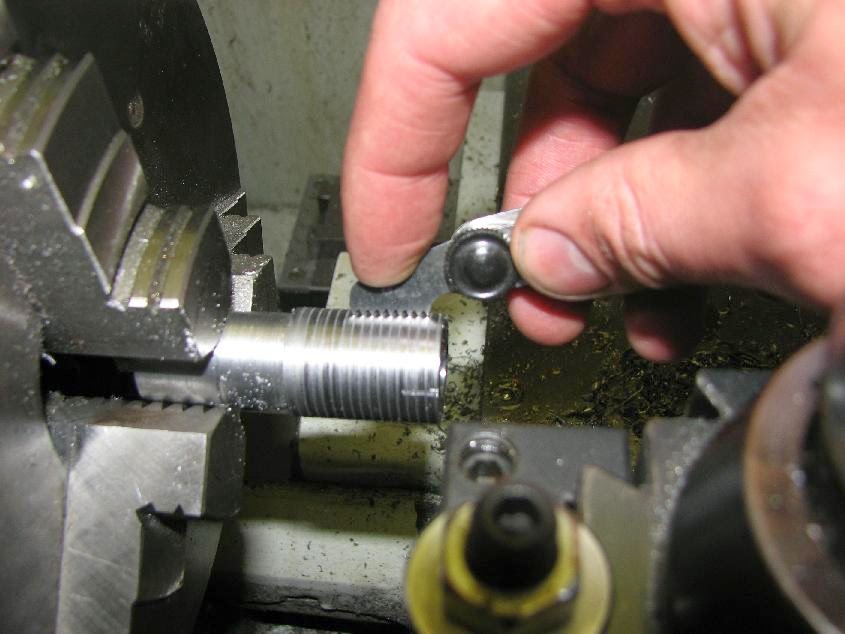
To check the suitability of the pitch is done turning lathe the screw thread with depth as thin as possible and then be checked with mall thread / pitch gauge.


7 turning thread
After the turning lathe screw can fit was done with the addition of an incision depth of 0.1 each. Fatherly finishing process adding a depth of 0.02 mm and an incision made ​​2-3 times at the same depth


Steps turning lathe inside thread.
In turning lathe inside thread on the same principle just different on the cutting tool and the Flat size of the turning lathe before threaded
1 Prepare working drawings
 

2 Prepare the cutting tools.
Cutting tools used another conduction
a. Center drill
Center drill is used to make holes in the prefix drilling holes in lathe
b. twist drill
Used to make the initial hole on the turning lathe thread
c. Tool bit ISO 8 / ISO 9
Once perforated with a twist drill is then done enlarged hole boring process with ISO 8 for through hole and ISO 9 for shoulder hole
d. Relief internal Groove tool bit
if thread not through it needs to make a groove for the release screw with a internal groove toolbit
e. Screw Tool bit inside
Used for turning lathe thread
 

3 Minor diameter lathe to thread
On the turning lathe screw in the hole that is the diameter of the major turner reduced pitch screw (threaded peak distance). For example Screw M16 x 2 the diameter of the hole made is 16-2 = 14 mm. and that the threaded fitting easier usually minor diameter plus 0.2 mm so that the diameter is 14.2 mm turner. to the next process in the same turning lathe with turning lathe screw threaded outside
 

4 Make relief threaded grooves
 

5 Set the peak spacing (pitch) desired
 

6 Checking the suitability of the pitch screw with pitch gauge
 

7 turning the thread until finish

Pics From :
 http://www.educationlite.com/lathe-machine-operations-shoulder-turning-thread-cutting-boring/
http://firearmsdesigner.com/?p=52 

Pembubutan ulir luar dan dalam / internal and external turning thread on lathe


Metode pembubutan ulir

1.       Metode konvensional
Metode konvensional adalah metode penguliran dengan gerakan pemakanan (penambahan kedalaman penyayatan/depth of cut) secara tegak lurus / menggunakan cross slide. 
2.     Metode penyayatan satu sisi
Metode penguliran ini dengan cara memiringkan top slide sebesar 60° dan menggunakan top slide sebagai gerakan pemakanan (depth of cut). Metode ini efisien untuk pembubutan ulir dengan ukuran yang besar

Prinsip Kerja pembubutan ulir adalah dengan menghubungkan putaran spindel dan putaran otomatis penguliran melalui roda gigi dan lead screw


Langkah-langkah pembubutan ulir luar.
1.     1. Mempersiapkan gambar kerja
Siapkan gambar kerja dan pahami dimensi-dimensi sesuai dengan permintaan gambar kerja. Hal ini penting agar pada waktu memproses pembubutan tidak terjadi kesalahan
2.      2. Mempersiapkan alat potong.
Beberapa alat potong yang perlu disiapkan adalah
a.       Pahat rata / ISO  6 untuk pembubutan diameter luar dari ulir
b.      Pahat muka chamfer / ISO 2 untuk pembubutan muka dan membuat pingul atau chamfer
c.       Pahat alur / ISO 7 untuk pembubutan alur pembebas pada waktu penguliran
d.      Pahat ulir metris untuk pembubutan ulir
3.      3. Membubut diameter mayor untuk ulir luar
Untuk pembubutan ulir luar diameter mayor dari ulir luar biasanya dikurangi sebesar 0,2 mm, dengan tujuan pada waktu proses penguliran terjadi built up chip pada puncak ulir maka diameter ulir luar akan pas dan mudah pada waktu pengepasan. Misalnya pembubutan ulir  M10 maka sebelum dilakukan penguliran diameter yang dibubut adalah 9,8 mm.

4.      4. Membuat alur pembebas ulir
Alur pembebas atau undercut perlu dibuat agar pada waktu penguliran pahat tidak menabrak pada bajian pojok / siku pada pembubutan ulir dengan diameter bertingkat dan agar pada waktu pengepasa bisa mepet dengan bagian pojok/ siku
5.      5. Mengatur jarak puncak (pitch) yang diinginkan
Aturlah pitch sesuai dengan tuntutan gambar dengan cara melihat tabel otomatis ulir dan memutar tuas roda gigi pada gearbox feed sesuai dengan tabel.

6.      6. Mengecek kesesuaian jarak puncak ulir
Untuk mengecek kesesuaian jarak puncak ulir maka dilakukan pembubutan ulir dengan kedalaman setipis mungkin dan kemudian dicheck dengan mal ulir / pitch gauge.

7.      7. Pembubutan ulir
Setelah sesuai maka pembubutan ulir dapat dilakuan dengan penambahan kedalaman 0,1 setiap penyayatan. Unutk proses finishing penambahan kedalaman sebesar 0,02 mm dan dilakukan 2-3 kali penyayatan pada kedalaman yang sama setelah selesai cek dengan mur atau ring thread gauge


Langkah-langkah pembubutan ulir dalam.
Pada pembubutan ulir dalam pada prinsipnya sama hanya berbeda pada alat potong dan ukuran pembubutan rata sebelum diulir 
1.       Mempersiapkan gambar kerja 
2.       Mempersiapkan alat potong.
Alat potong yang digunakan antaran lain
a.       Center drill
Center drill digunakan untuk membuat awalan lubang pada pengeboran lubang di mesin bubut
b.      Twist drill
Digunakan untuk membuat lubang awal pada proses pembubutan ulir dalam
c.       Pahat ISO 8 / ISO 9
Setelah dilubangi dengan twist drill maka dilakukan proses boring yaitu pembesaran lubang dengan ISO 8 untuk lubang tembus dan ISO 9 untuk lubang bertingkat
d.      Pahat alur dalam
Pada lubang bertingkat atau ulir tidak tembus maka perlu dibuat alur untuk pembebasan ulir dengan pahat alur dalam
e.      Pahat Ulir dalam
Digunakan untuk pembubutan ulir dalam
3.       Membubut diameter Minor untuk ulir dalam
Pada pembubutan ulir dalam maka diameter lubang yang dibubut adalah sebesar diameter mayor ulir  dikurangi pitch (jarak puncak ulir). Misalnya Ulir M16 x 2 maka diameter lubang yang dibuat adalah 16 – 2 = 14 mm. dan agar dalam pengepasan ulir lebih mudah biasanya diameter minor ditambah 0,2 mm sehingga diameter yang dibubut adalah 14,2 mm. untuk selanjutnya proses pembubutan ulir dalam sama dengan pembubutan ulir luar

4.       Membuat alur pembebas ulir
5.       Mengatur jarak puncak (pitch) yang diinginkan
6.       Mengecek kesesuaian jarak puncak ulir
7.       Pembubutan ulir


Sumber gambar :
http://firearmsdesigner.com/?p=52
http://www.educationlite.com/lathe-machine-operations-shoulder-turning-thread-cutting-boring/